How highway corridor survey works
What happens between flying a road corridor and receiving a map your design team can use?
- Service
- RGB mapping
- Reading
- 7 steps, limits stated
In short
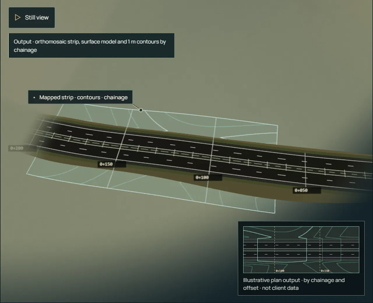
A highway corridor survey maps a long, narrow strip along a road alignment. With RGB photogrammetry, overlapping aerial photographs are matched and processed into an orthomosaic, a surface model and contours, then referenced to the project chainage.
From alignment to deliverable
Define the alignment and corridor
Agree the centreline, the chainage start and direction, and how wide the mapped corridor must be. The working corridor is a survey extent, not a legal right-of-way.
Plan capture and control
Set flight lines, height and overlap for the required detail. Choose how positions are established and checked: RTK or PPK positioning, ground control points, independent checkpoints, or a combination.
Collect overlapping photographs
Each photograph covers a footprint on the ground. Consecutive footprints overlap heavily along the line, and neighbouring lines overlap across it.
Match and reference
Software finds the same features in several photographs. Those matches, with the camera positions and any control, solve where each photograph was taken and where each feature sits.
Build the mapped outputs
The solved photographs produce a dense point cloud, a surface model, an orthomosaic and derived contours.
Review against chainage
Outputs are checked against the control and checkpoints, then organised along the alignment so a location can be found by its chainage and offset.
Deliver the agreed files
Formats, coordinate system, tiling and any drawings are agreed at scoping, not assumed.
Typical outputs
- Orthomosaic
- A scale-corrected image of the corridor, viewed from directly above.
- Point cloud and surface model (DSM)
- The visible surface, including vehicles, structures and vegetation.
- Terrain model (DTM) and contours
- Bare ground where the ground is visible and the method supports it.
- Chainage-referenced data
- Sections, features or drawings located by chainage and offset, as scoped.
Limitations
- Photographs record what the camera can see. Vegetation, traffic, shadow and water hide or distort the ground.
- Accuracy depends on the survey design, positioning, control and checks. Imagery alone does not establish survey accuracy.
- Flights need permissions, safe access and suitable weather; live traffic affects what can be captured.
- Deliverables, formats and tolerances must be agreed for each project.
- Where dense vegetation hides the ground, LiDAR or a ground survey may be the better method.
Terms
- Chainage
- Distance measured along the alignment from a defined start, written as kilometres + metres (0+150 is 150 m).
- Working corridor
- The strip to be mapped. It is not a legal right-of-way or property boundary.
- Overlap
- How much consecutive photographs share. High overlap gives enough matching features to reconstruct the surface.
- Control and checkpoints
- Surveyed points used to fix and to independently check the result. Whether they are needed depends on the survey design.
- DSM and DTM
- A surface model includes what stands on the ground; a terrain model represents the ground itself.
Planning a corridor survey?
Discuss a highway corridor survey